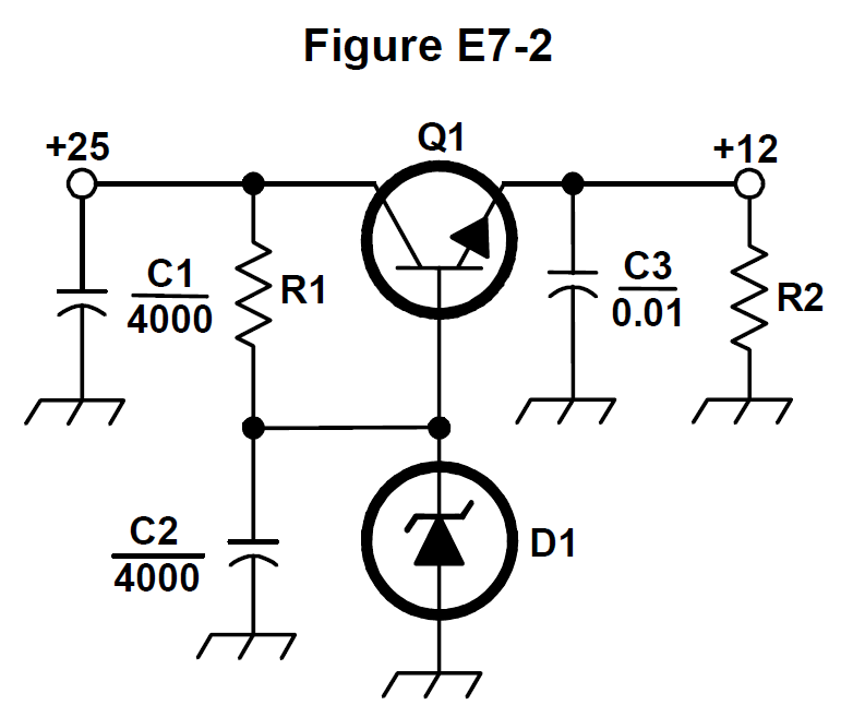
What is the purpose of Q1 in the circuit shown in Figure E7-2?
It provides negative feedback to improve regulation
It provides a constant load for the voltage source
It controls the current to keep the output voltage constant✓Richtige Antwort
It provides regulation by switching or “chopping” the input DC voltage
Erklärung
In Figure E7-2, Q1 sits in series between the +25 V input and the +12 V output with its base clamped by the D1 reference, so it behaves as a variable resistance that passes the load current. It adjusts its conduction to hold the output voltage constant as line and load change.