QuestenaUn entraînement qui indique quoi revoir ensuite
Question 389

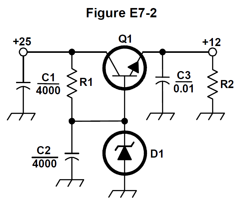
What type of circuit is shown in Figure E7-2?

Schematic of a circuit with transistor Q1, diode D1, resistors R1 and R2, and capacitors C1, C2, and C3 between a labeled supply input and output.
  1. Switching voltage regulator
  2. Common emitter amplifier
  3. Linear voltage regulatorBonne réponse
  4. Common base amplifier

Explication

Figure E7-2 shows a series pass transistor whose base is held by a Zener reference, with filter capacitors on input and output and a load resistor: +25 V goes in and +12 V comes out. Nothing is switched or chopped and the transistor conducts continuously, so this is a linear voltage regulator.
Continuer avec ce test

Commencer l’entraînement
Question 389: What type of circuit is shown in Figure E7-2? · FCC Amateur Extra Class (Element 4) · Questena