QuestenaPractice that shows what to review next
Question 312

In Figure E6-3, which is the schematic symbol for a NOR gate?
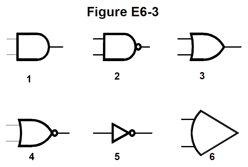
Six schematic symbols of digital logic elements, numbered 1 through 6.
  1. 1
  2. 2
  3. 3
  4. 4Correct answer

Explanation

Symbol 4 has the concave input side and pointed output of an OR gate plus an inversion bubble, which makes it a NOR. Symbol 3 is that same OR body without the bubble, symbol 1 is a plain AND, and symbol 2 is the AND body with a bubble, which is a NAND.

Continue with this test

Start practice
Question 312: In Figure E6-3, which is the schematic symbol for a NOR… · FCC Amateur Extra Class (Element 4) · Questena