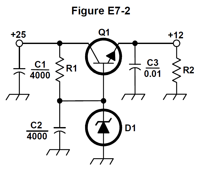
What is the purpose of C2 in the circuit shown in Figure E7-2?
It bypasses rectifier output ripple around D1✓Correct answer
It is a brute force filter for the output
To prevent self-oscillation
To provide fixed DC bias for Q1
Explanation
In Figure E7-2, C2 is connected from the D1 reference node to ground, in parallel with the Zener. Ripple left over from the rectifier and the Zener's own noise are therefore shunted to ground instead of being passed on to the output by Q1.